Basic Theory Of Computer Science
|
|
This article is intend to explain to new users, who are unfamiliar with computer theory, basic concepts of computing and computer systems organization and structure.
The idea of the creation of this article was inspired by the general disorganization of such kind of theoretic articles and pages at OSDev.org. And as long as theory is very important for beginners (and as long as they generally never ever read serious books), this chaotic structure of theoretic material will cause problems in comprehensive study of OS development. But this article is meant to fix the problem
It's impossible to study all the topics of physics, circuitry and computer science in within one article. Instead, all these subjects will be briefly touched. To do so in organized order, we must divide system into layers, each having its own rules and aims. To do so, we must manage complexity of the system
Managing the complexity of electronic systems
The system you are using to read this article (let me guess it's a personal computer) is one of most complex systems ever created by the mankind. Just imagine hundreds of billions transistors on several separate integrated circuits joint together and operating at gigahertz rates, running hundreds of millions lines of code in a blink of an eye - hundreds of thousands of computer scientists, engineers and programmers united their efforts to make this miracle come true in less than 80 years...
However, I bet you are not experiencing any kind of trouble with using such a "miracle". The main reason of it is that, despite you don't realize it really, you are managing complexity of your system. It have let you to open this article in few mouse clicks without having to keep in mind details of, for example, the HTML protocol your browser used to obtain this article from the website.
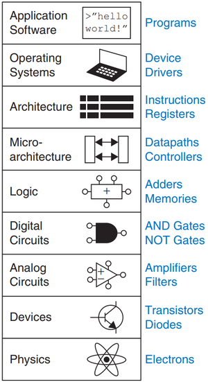
Instead, you delegate this task to your web-browser - this is an application software![]() , which uses abilities of operating system
, which uses abilities of operating system![]() to run, which uses definitions and rules of architecture
to run, which uses definitions and rules of architecture ![]() layers, and so on
layers, and so on
Usually developers define 9 layers of abstraction for an average electronic computing system:
- Application Software

- Programs, which use operating system features to solve user problems
- Operating System

- Operates computer hardware, manage system resources and provide API and drivers for application software
- Architecture
 (also known as ISA)
- Describes electronic system from programmer's perspective. Defines instruction set, visible registers. Is implemented by microarchitecture
- Microarchitecture

- Implements an architecture using logic elements
- Logic

- Combines digital circuits to create functional blocks, such as adders, multiplexers and so on.
- Digital Circuits

- Uses analog circuits to create models of the digital circuits, which can be used in digital design
- Analog Circuits

- Combines devices to create circuits with desired properties
- Devices

- Uses physical models to create devices, such as transistors and diodes, usable in circuits
- Physics

- Explores the world and systematizes obtained knowledge to laws and theories which can be relatively easily studied by other persons
As you can see, each abstraction level use models and features of underlying level (e.g. logic uses digital circuits as much as application software uses operating system features) Also, each level hides details of implementation from the overlying level (e.g. user do not have to bother about representing their requests in "computer" form as long as application software provides the human-understandable GUI)
And it means, that each layer accomplishes two tasks:
- Provides simplified interfaces for overlying layers
- For example, there are no files on the hard disk of your PC - only some bytes written to it in the specified order. File is just an abstract model of storing files on the physical drive, implemented by a filesystem - one of the parts of your operating system. So, filesystem provides a very convenient interface for application software, by implementing a simple file I/O
- Hides implementation details from overlying layer and manages them
- For example, filesystem also contains drivers for different types of storage devices, such as hard drives, optical drives and so on. Each one have its own interface to handle. However, you, as a user, don't want to keep these details in mind. So, filesystem takes care of it, hiding such a details from user, managing all that low-level things by itself
Since this tutorial was written for OS and applications developers, detailed description of three lower levels of hierarchy will be skipped
Digital Circuits
As you surely know, all the modern computers are implemented using digital logic, but why?
There are few major reasons:
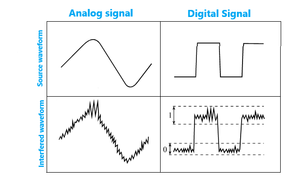
- Digital signals are more stable and reliable than analog ones, because they are less prone for distortions, noises, and interferences.
- Digital circuits are easy and cheap to design and implement in hardware using different technologies
- Different digital circuits can be easily combined, creating more complex circuits.
These facts are the main reasons of domination of the digital logic over analog today.
So, what helps digital logic to attain such appealing properties? It operates only two signal states - LOW and HIGH, instead of wide spectrum of voltages as in analog circuits.
Contrary to popular belief - these do not directly correspond to "lack of voltage" and "some voltage". This is just not how most electronic components (e.g. transistors) function. In reality, LOW is any "trivial" voltage, and HIGH is any "nontrivial" voltage.
The states of LOW and HIGH may also be titled 0 and 1.
The end goal of a digital circuit is usually to reach a digital end device, that also categorizes voltages as LOW and HIGH. Data is usually stored in digital registers. The data is then changed by electronic components in the circuit, and given back to the registers or the end device. This allows for implementing various models of computation.
Logic
To properly modify digital data using a digital circuit, it is useful to have a logical framework with a finite amount of well-defined operations that combined may yield a plethora of results.
The standard logical framework used in modern digital circuitry is Boolean algebra. A Boolean algebra is a space with two possible values: 0 and 1. It is equipped with a negation, addition and multiplication.
Negation is an operation that performed on 0 returns 1 and performed on 1 returns 0.
Addition is an operation defined by the following:
- 0 + 0 = 0
- 0 + 1 = 1
- 1 + 0 = 1
- 1 + 1 = 1
Furthermore, this operation is associative.
Multiplication is an operation defined by the following:
- 0 * 0 = 0
- 0 * 1 = 0
- 1 * 0 = 0
- 1 * 1 = 1
This operation is also associative.
In computer science, negation is usually called a NOT gate, addition is called an OR gate, and multiplication is called an AND gate. They can all be built from simple electronic components.
There are more gates that can be created out of those operations. For example, a well-known gate is XOR, defined for any a, b in a Boolean algebra as not(a) * b + a * not(b). From a practical perspective, XOR (or the eXclusive OR gate) is a way to perform the OR operation without triggering 1 for the 1,1 case.
These gates, often also called logic gates, can be chained together to create more complex mechanisms. For example, a common mechanism is called a half-adder. It adds two bits to each other.
- 0 + 0 = 00
- 0 + 1 = 01
- 1 + 0 = 01
- 1 + 1 = 10
It is very easy to implement. The first bit simply works like an AND gate, while the second bit works like a XOR gate.


