Paging
|
The factual accuracy of this article or section is disputed. |
Paging is a system which allows each process to see a full virtual address space, without actually requiring the full amount of physical memory to be available or present. 32-bit x86 processors support 32-bit virtual addresses and 4-GiB virtual address spaces, and current 64-bit processors support 48-bit virtual addressing and 256-TiB virtual address spaces. Intel has released documentation for a extension to 57-bit virtual addressing and 128-PiB virtual address spaces. Currently, implementations of x86-64 have a limit of between 4 GiB and 256 TiB of physical address space (and an architectural limit of 4 PiB of physical address space).
In addition to this, paging introduces the benefit of page-level protection. In this system, user processes can only see and modify data which is paged in on their own address space, providing hardware-based isolation. System pages are also protected from user processes. On the x86-64 architecture, page-level protection now completely supersedes Segmentation as the memory protection mechanism. On the IA-32 architecture, both paging and segmentation exist, but segmentation is now considered 'legacy'.
Once an Operating System has paging, it can also make use of other benefits and workarounds, such as linear framebuffer simulation for memory-mapped IO and paging out to disk, where disk storage space is used to free up physical RAM.
32-bit Paging (Protected Mode)
MMU
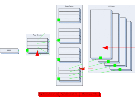
Paging is achieved through the use of the Memory Management Unit (MMU). On the x86, the MMU maps memory through a series of tables, two to be exact. They are the paging directory (PD), and the paging table (PT).
Both tables contain 1024 4-byte entries, making them 4 KiB each. In the page directory, each entry points to a page table. In the page table, each entry points to a 4 KiB physical page frame. Additionally, each entry has bits controlling access protection and caching features of the structure to which it points. The entire system consisting of a page directory and page tables represents a linear 4-GiB virtual memory map.
Translation of a virtual address into a physical address first involves dividing the virtual address into three parts: the most significant 10 bits (bits 22-31) specify the index of the page directory entry, the next 10 bits (bits 12-21) specify the index of the page table entry, and the least significant 12 bits (bits 0-11) specify the page offset. The then MMU walks through the paging structures, starting with the page directory, and uses the page directory entry to locate the page table. The page table entry is used to locate the base address of the physical page frame, and the page offset is added to the physical base address to produce the physical address. If translation fails for some reason (entry is marked as not present, for example), then the processor issues a page fault.
Page Directory
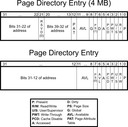
The topmost paging structure is the page directory. It is essentially an array of page directory entries that take the following form.
When PS=0, the page table address field represents the physical address of the page table that manages the four megabytes at that point. Please note that it is very important that this address be 4-KiB aligned. This is needed, due to the fact that the last 12 bits of the 32-bit value are overwritten by access bits and such. Similarly, when PS=1, the address must be 4-MiB aligned.
- PAT, or 'Page Attribute Table'. If PAT is supported, then PAT along with PCD and PWT shall indicate the memory caching type. Otherwise, it is reserved and must be set to 0.
- G, or 'Global' tells the processor not to invalidate the TLB entry corresponding to the page upon a MOV to CR3 instruction. Bit 7 (PGE) in CR4 must be set to enable global pages.
- PS, or 'Page Size' stores the page size for that specific entry. If the bit is set, then the PDE maps to a page that is 4 MiB in size. Otherwise, it maps to a 4 KiB page table. Please note that 4-MiB pages require PSE to be enabled.
- D, or 'Dirty' is used to determine whether a page has been written to.
- A, or 'Accessed' is used to discover whether a PDE or PTE was read during virtual address translation. If it has, then the bit is set, otherwise, it is not. Note that, this bit will not be cleared by the CPU, so that burden falls on the OS (if it needs this bit at all).
- PCD, is the 'Cache Disable' bit. If the bit is set, the page will not be cached. Otherwise, it will be.
- PWT, controls Write-Through' abilities of the page. If the bit is set, write-through caching is enabled. If not, then write-back is enabled instead.
- U/S, the 'User/Supervisor' bit, controls access to the page based on privilege level. If the bit is set, then the page may be accessed by all; if the bit is not set, however, only the supervisor can access it. For a page directory entry, the user bit controls access to all the pages referenced by the page directory entry. Therefore if you wish to make a page a user page, you must set the user bit in the relevant page directory entry as well as the page table entry.
- R/W, the 'Read/Write' permissions flag. If the bit is set, the page is read/write. Otherwise when it is not set, the page is read-only. The WP bit in CR0 determines if this is only applied to userland, always giving the kernel write access (the default) or both userland and the kernel (see Intel Manuals 3A 2-20).
- P, or 'Present'. If the bit is set, the page is actually in physical memory at the moment. For example, when a page is swapped out, it is not in physical memory and therefore not 'Present'. If a page is called, but not present, a page fault will occur, and the OS should handle it. (See below.)
The remaining bits 9 through 11 (if PS=0, also bits 6 & 8) are not used by the processor, and are free for the OS to store some of its own accounting information. In addition, when P is not set, the processor ignores the rest of the entry and you can use all remaining 31 bits for extra information, like recording where the page has ended up in swap space. When changing the accessed or dirty bits from 1 to 0 while an entry is marked as present, it's recommended to invalidate the associated page. Otherwise, the processor may not set those bits upon subsequent read/writes due to TLB caching.
Setting the PS bit makes the page directory entry point directly to a 4-MiB page. There is no paging table involved in the address translation. Note: With 4-MiB pages, whether or not bits 20 through 13 are reserved depends on PSE being enabled and how many PSE bits are supported by the processor (PSE, PSE-36, PSE-40). CPUID should be used to determine this. Thus, the physical address must also be 4-MiB-aligned. Physical addresses above 4 GiB can only be mapped using 4 MiB PDEs.
Page Table
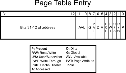
In each page table, as it is, there are also 1024 entries. These are called page table entries, and are very similar to page directory entries.
The first item, is once again, a 4-KiB aligned physical address. Unlike previously, however, the address is not that of a page table, but instead a 4 KiB block of physical memory that is then mapped to that location in the page table and directory. Note that the PAT bit is bit 7 instead of bit 12 as in the 4 MiB PDE.
Example
Say the kernel is loaded to 0x100000. However, it needed to be remapped to 0xC0000000. After loading the kernel, it'll initiate paging, and set up the appropriate tables. (See Higher Half Kernel) After Identity Paging the first megabyte, it'll need to create a second table (ie. at entry #768 in the paging directory.) to map 0x100000 to 0xC0000000. The code may be like:
 mov eax, 0x0
 mov ebx, 0x100000
 .fill_table:
      mov ecx, ebx
      or ecx, 3
      mov [table_768+eax*4], ecx
      add ebx, 4096
      inc eax
      cmp eax, 1024
      jne .fill_table
64-Bit Paging
Paging in long mode is similar to that of 32-bit paging, except Physical Address Extension (PAE) is required. Registers CR2 and CR3 are extended to 64 bits. Instead of just having to utilize 3 levels of page maps: page directory pointer table, page directory, and page table, a fourth page-map table is used: the level-4 page map table (PML4). This allows a processor to map 48-bit virtual addresses to 52-bit physical addresses. If level-5 page maps are supported and enabled, then a fifth page-map table, the level-5 page map table (PML5), allows the processor to map 57-bit virtual addresses to 52-bit physical addresses. Both the PML4 and PML5 contain 512 64-bit entries of which each may point to a lower-level page map table. Do note that with each additional level of paging, virtual addressing becomes slower, especially in the case of TLB cache misses.
Virtual addresses in 64-bit mode must be canonical, that is, the upper bits of the address must either be all 0s or all 1s. For systems supporting 48-bit virtual address spaces, the upper 16 bits must be the same, and for systems supporting 57-bit virtual addresses, the upper 7 bits must match. Although 32-bit code running in long mode (compatibility mode) is still limited to 32-bit virtual addresses, they can still map to a 52-bit physical addresses.
Page Map Table Entries
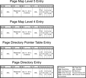
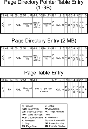
New bits have been added to page map table entries for long-mode paging:
- XD, or 'Execute Disable'. If the NXE bit (bit 11) is set in the EFER register, then instructions are not allowed to be executed at addresses within the page whenever XD is set. If EFER.NXE bit is 0, then the XD bit is reserved and should be set to 0.
- PK, or 'Protection Key'. The protection key is a 4-bit corresponding to each virtual address that is used to control user-mode and supervisor-mode memory accesses. If the PKE bit (bit 22) in CR4 is set, then the PKRU register is used for determining access rights for user-mode based on the protection key. If the PKS bit (bit 24) is set in CR4, then the PKRS register is used for determining access rights for supervisor-mode based on the protection key. A protection key allows the system to enable/disable access rights for multiple page entries across different address spaces at once.
M signifies the physical address width supported by a processor using PAE. Currently, up to 52 bits are supported, but the actual supported width may be less.
Bits marked as reserved must all be set to 0, otherwise, a page fault will occur with a reserved error code.
Support for 1 GiB pages, (NX) execute disable, (PKS/PKU) protection keys for supervisor-mode and user-mode pages, shadow stack pages, (M) physical address width, virtual address width, (PAT) page attribute table, (PCID) process context identifiers, and (LA57) 5-level paging can be determined with the CPUID instruction (EAX:0x01; EAX:0x07, ECX=0x00; EAX:0x80000001; EAX:0x80000008).
Process Context Identifiers
If process context ids (PCID) are supported, then bits 0-11 of CR3 specify the process context id. Otherwise, bit 3 is PWT for PML4, and bit 4 is PCD for PML4. PCIDs are used to control TLB caching across multiple address spaces. The INVPCID instruction uses PCIDs to allow more control over page invalidation.
Enabling
32-bit Paging
Enabling paging is actually very simple. All that is needed is to load CR3 with the address of the page directory and to set the paging (PG) and protection (PE) bits of CR0.
 mov eax, page_directory
 mov cr3, eax

 mov eax, cr0
 or eax, 0x80000001
 mov cr0, eax
Note: setting the paging flag when the protection flag is clear causes a general protection exception. Also, once paging has been enabled, any attempt to enable long mode by setting LME (bit 8) of the EFER register will trigger a GPF. The CR0.PG must first be cleared before EFER.LME can be set.
If you want to set pages as read-only for both userspace and supervisor, replace 0x80000001 above with 0x80010001, which also sets the WP bit.
To enable PSE (4 MiB pages) the following code is required.
 mov eax, cr4
 or eax, 0x00000010
 mov cr4, eax
64-bit Paging
Enabling paging in long mode requires a few more additional steps. Since it is not possible to enter long mode without paging with PAE active, the order in which one enables the bits are important. Firstly, paging must not be active (i.e. CR0.PG must be cleared.) Then, CR4.PAE (bit 5) and EFER.LME (bit 8 of MSR 0xC0000080) are set. If 57-bit virtual addresses are to be enabled, then CR4.LA57 (bit 12) is set. Finally, CR0.PG is set to enable paging.
  ; Skip these 3 lines if paging is already disabled
  mov ebx, cr0
  and ebx, ~(1 << 31)
  mov cr0, ebx

  ; Enable PAE
  mov edx, cr4
  or  edx, (1 << 5)
  mov cr4, edx

  ; Set LME (long mode enable)
  mov ecx, 0xC0000080
  rdmsr
  or  eax, (1 << 8)
  wrmsr

  ; Replace 'pml4_table' with the appropriate physical address (and flags, if applicable)
  mov eax, pml4_table
  mov cr3, eax

  ; Enable paging (and protected mode, if it isn't already active)
  or ebx, (1 << 31) | (1 << 0)
  mov cr0, ebx

  ; Now reload the segment registers (CS, DS, SS, etc.) with the appropriate segment selectors...

  mov ax, DATA_SEL
  mov ds, ax
  mov es, ax
  mov fs, ax
  mov gs, ax

  ; Reload CS with a 64-bit code selector by performing a long jmp

  jmp CODE_SEL:reloadCS

[BITS 64]
reloadCS:
  hlt   ; Done. Replace these lines with your own code
  jmp reloadCS
Once paging has been enabled, you cannot switch from 4-level paging to 5-level paging (and vice-versa) directly. The same is true for switching to legacy 32-bit paging. You must first disable paging by clearing CR0.PG before making changes. Failure to do so will result in a general protection fault.
Physical Address Extension
All Intel processors since Pentium Pro (with exception of the Pentium M at 400 Mhz) and all AMD since the Athlon series implement the Physical Address Extension (PAE). This feature allows you to access up to 4 PiB (252) of RAM. You can check for this feature using CPUID. Once checked, you can activate this feature by setting bit 5 in CR4.
For legacy 32-bit PAE, the CR3 register points to a page directory pointer table (PDPT) of 4 64-bit entries, each one pointing to a page directory made of 4096 bytes (like in normal paging), divided into 512 64-bit entries, each pointing to a 4096-byte page table, divided into 512 64bit page entries. Keep in mind that virtual addresses are still limited to 4 GiB (232 bytes).
For 4-level and 5-level PAE, as used in compatibility mode and long mode, the CR3 register points to the top-level page map table: the PML4 table and PML5 table, respectively. Each of the page map tables: PML5 table, PML4 table, page directory pointer table, page directory, page table, contain 512 64-bit entries.
If paging is enabled then PAE must also be enabled before entering long mode. Attempting to enter long mode with CR0.PG set and CR4.PAE cleared will trigger a general protection fault.
Usage
Due to the simplicity in the design of paging, it has many uses.
Virtual Address Spaces
In a paged system, each process may execute in its own area of memory, without any chance of affecting any other process's memory, or the kernel's. Two or more processes may opt to share memory by mapping the same physical page(s) to addresses in their own address spaces. The virtual address of each mapping do not need to be the same. Consequently, a virtual address in one address space won't point to the same data in other address spaces, in general.
Virtual Memory
Because paging allows for the dynamic handling of unallocated page tables, an OS can swap entire pages, not in current use, to the hard drive where they can wait until they are called. In the mean time, however, the physical memory that they were using can be used elsewhere. In this way, the OS can manipulate the system so that programs actually seem to have more RAM than there actually is.
More...
Manipulation
The CR3 value, that is, the value containing the address of the page directory, is in physical form. Once, then, the computer is in paging mode, only recognizing those virtual addresses mapped into the paging tables, how can the tables be edited and dynamically changed?
Many prefer to map the last PDE to itself. The page directory will look like a page table to the system. To get the physical address of any virtual address in the range 0x00000000-0xFFFFF000 is then just a matter of:
void *get_physaddr(void *virtualaddr) {
    unsigned long pdindex = (unsigned long)virtualaddr >> 22;
    unsigned long ptindex = (unsigned long)virtualaddr >> 12 & 0x03FF;

    unsigned long *pd = (unsigned long *)0xFFFFF000;
    // Here you need to check whether the PD entry is present.

    unsigned long *pt = ((unsigned long *)0xFFC00000) + (0x400 * pdindex);
    // Here you need to check whether the PT entry is present.

    return (void *)((pt[ptindex] & ~0xFFF) + ((unsigned long)virtualaddr & 0xFFF));
}
To map a virtual address to a physical address can be done as follows:
void map_page(void *physaddr, void *virtualaddr, unsigned int flags) {
    // Make sure that both addresses are page-aligned.

    unsigned long pdindex = (unsigned long)virtualaddr >> 22;
    unsigned long ptindex = (unsigned long)virtualaddr >> 12 & 0x03FF;

    unsigned long *pd = (unsigned long *)0xFFFFF000;
    // Here you need to check whether the PD entry is present.
    // When it is not present, you need to create a new empty PT and
    // adjust the PDE accordingly.

    unsigned long *pt = ((unsigned long *)0xFFC00000) + (0x400 * pdindex);
    // Here you need to check whether the PT entry is present.
    // When it is, then there is already a mapping present. What do you do now?

    pt[ptindex] = ((unsigned long)physaddr) | (flags & 0xFFF) | 0x01; // Present

    // Now you need to flush the entry in the TLB
    // or you might not notice the change.
}
Unmapping an entry is essentially the same as above, but instead of assigning the pt[ptindex] a value, you set it to 0x00000000 (i.e. not present). When the entire page table is empty, you may want to remove it and mark the page directory entry 'not present'. Of course you don't need the 'flags' or 'physaddr' for unmapping.
Page Faults
A page fault exception is caused when a process is seeking to access an area of virtual memory that is not mapped to any physical memory, when a write is attempted on a read-only page, when accessing a PTE or PDE with the reserved bit or when permissions are inadequate. A page fault can either be pure, which occurs when the faulting process has permission to access the page, or invalid, which is due to a protection violation. Pure page faults aren't errors, but are resolved through the page fault handler by performing the appropriate map operation and/or page swap.
Handling
The CPU pushes an error code on the stack before firing a page fault exception. The error code must be analyzed by the exception handler to determine how to handle the exception. The following bits are the only ones used, all others are reserved.
Bit 0 (P) is the Present flag.
Bit 1 (R/W) is the Read/Write flag.
Bit 2 (U/S) is the User/Supervisor flag.
Bit 3 (RSVD) indicates whether a reserved bit was set in some page-structure entry
Bit 4 (I/D) is the Instruction/Data flag (1=instruction fetch, 0=data access)
Bit 5 (PK) indicates a protection-key violation
Bit 6 (SS) indicates a shadow-stack access fault
Bit 15 (SGX) indicates an SGX violaton
The combination of these flags specify the details of the page fault and indicate what action to take:
US RW  P - Description
0  0  0 - Supervisory process tried to read a non-present page entry
0  0  1 - Supervisory process tried to read a page and caused a protection fault
0  1  0 - Supervisory process tried to write to a non-present page entry
0  1  1 - Supervisory process tried to write a page and caused a protection fault
1  0  0 - User process tried to read a non-present page entry
1  0  1 - User process tried to read a page and caused a protection fault
1  1  0 - User process tried to write to a non-present page entry
1  1  1 - User process tried to write a page and caused a protection fault
When the CPU fires a page-not-present exception the CR2 register is populated with the linear address that caused the exception. The upper 10 bits specify the page directory entry (PDE) and the middle 10 bits specify the page table entry (PTE). First check the PDE and see if it's present bit is set, if not setup a page table and point the PDE to the base address of the page table, set the present bit and iretd. If the PDE is present then the present bit of the PTE will be cleared. You'll need to map some physical memory to the page table, set the present bit and then iretd to continue processing.
INVLPG
INVLPG is an instruction available since the i486 that invalidates a single page in the TLB. Intel notes that this instruction may be implemented differently on future processors, but that this alternate behavior must be explicitly enabled. INVLPG modifies no flags.
NASM example:
invlpg [0]
Inline assembly for GCC (from Linux kernel source):
static inline void __native_flush_tlb_single(unsigned long addr) {
   asm volatile("invlpg (%0)" ::"r" (addr) : "memory");
}
This only invalidates the page on the current processor. If you're using SMP, you'll need to send an IPI to the other processors so that they can also invalidate the page (this is called a TLB shootdown; it's very slow), making sure to avoid any nasty race conditions. You may only want to do this when removing a mapping, and just make your page fault handler invalidate a page if it you didn't invalidate a mapping addition on that processor by looking through the page directory, again avoiding race conditions.
When you modify an entry in the page directory, rather than just a page table, you'll need to invalidate each page in the table. Alternatively, you could reload CR3 which will invalidates the whole directory, but this may be slower. (TODO time this)
Paging Tricks
The processor always fires a page fault exception when the present bit is cleared in the PDE or PTE regardless of the address. This means the contents of the PTE or PDE can be used to indicate a location of the page saved on mass storage and to quickly load it. When a page gets swapped to disk, use these entries to identify the location in the paging file where they can be quickly loaded from then set the present bit to 0. Similarly, blocks from disk can be mapped to memory this way. When a process accesses the memory-mapped region, a page fault occurs. The fault handler reads the appropriate tables, loads the disk block(s) into a page, and maps it. The process can then read/write to memory as if it were accessing the device directly. The contents of the page would then be written back to disk to save the changes.
For memory efficiency, two or more processes can share pages as read-only. If one process were to write to its page, then a page fault would occur and the system could duplicate the page and then mark it as read-write. This is known as copy-on-write (COW). Copy-on-write allows the system to delay memory allocation until a process actually requires it, preventing unnecessary copying.
PAT
The Page Attribute Table determines caching attributes on a page granularity. This is similar to MTRRs, but those apply to physical addresses and are more limited.
The PAT is set via the IA32_PAT_MSR MSR (0x277). It has 8 entries, taking the low order 3 bits of each byte, in standard little endian order. So the high byte is PAT7, low byte is PAT0.
The following are the different caching types.
| Number | Name | Description |
|---|---|---|
| 0 | UC — Uncacheable | All accesses are uncacheable. Write combining is not allowed. Speculative accesses are not allowed. |
| 1 | WC — Write-Combining | All accesses are uncacheable. Write combining is allowed. Speculative reads are allowed. |
| 4 | WT — Writethrough | Reads allocate cache lines on a cache miss. Cache lines are not allocated on a write miss.
Write hits update the cache and main memory. |
| 5 | WP — Write-Protect | Reads allocate cache lines on a cache miss. All writes update main memory.
Cache lines are not allocated on a write miss. Write hits invalidate the cache line and update main memory. |
| 6 | WB — Writeback | Reads allocate cache lines on a cache miss, and can allocate to either the shared,
exclusive, or modified state. Writes allocate to the modified state on a cache miss. |
| 7 | UC- — Uncached | Same as uncacheable, except that this can be overriden by Write-Combining MTRRs. |
The PAT has a reset value of 0x0007040600070406. This ensures compatibility with non-PAT usage. This corresponds to the following:
| UC | UC- | WT | WB | UC | UC- | WT | WB |
The PAT is indexed by the three page table bits:
| PAT | PCD | PWT |
The PAT bit is reserved when there isn't a PAT, and the default value of the MSR ensures backwards comaptibility with the PCD and PWT bit.
You will need to modify the PAT if you want Write-Combining cache, which is very useful for framebuffers.
See Also
Articles
- Identity Paging
- Page Frame Allocation
- Setting Up Paging
- Page Tables
- Memory Management
- Memory Management Unit
- Page Coloring
