Raspberry Pi
|
|

|
This page or section refers to its readers or editors using I, my, we or us. It should be edited to be in an encyclopedic tone. |
|
This article was written like there is only one author. This is a wiki, not a personal site. You can help the wiki by editing this article to remove mentions of authors. |
This is a tutorial on bare-metal [OS] development on the Raspberry Pi. This tutorial is written specifically for the Raspberry Pi Model B Rev 2 because the author has no other hardware to test on. But so far the models are basically identical for the purpose of this tutorial (Rev 1 has 256MB ram, Model A has no ethernet).
This is the authors very first ARM system and we learn as we write without any prior knowledge about ARM. Experience in Linux/Unix (very important) and C/C++ language (incredibly important, including how to use inline assembler) is assumed and required. This is not a tutorial about how to build a kernel but a simple intro in how to get started on the RPi.
Preparations
Materials
You will need a:
- Raspberry Pi, RPi in short.
- SD Card to boot from.
- A SD Card reader so you can write to the SD Card from your developement system.
- A serial adaptor for the RPi.
- Power from an external Power Supply, USB or the Serial Adaptor.
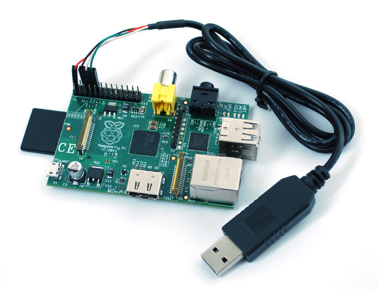
Serial adaptor
The RPi has 2 serial ports (UARTs). This tutorial only concerns itself with UART0, called simply UART or serial port. UART1 is ignored from now on. The basic UART onboard uses a 3.3V TTL and is connected to some of the GPIO pins labeled "P1" on the board. x86 PCs and MACs do use 5V TTL so you need some adaptor to convert the TTL. A USB to TTL Serial Cable - Debug/Console Cable for Raspberry Pi with separate connectors per lead, like commercial RPi serial adaptor, is recommended.. Which is then connected to the RPi like this. The slightly cheaper PL2303HX adapter was found usable, but seems to be unreliable if connected to an USB port with an extension cable (a USB 2.0 hub might remedy this).
Note: The serial adaptor I use provides both a 0V and 5V lead (black and red) which provide power to the RPi. No extra power supply is needed besides this.
Alternatively, you can use the FTDI chip on an Arduino (or clone thereof). Connect RX on the Arduino to RX on the Pi, TX to TX and GND to GND, then connect the Arduino's reset pin to ground to prevent code in flash from interfering. Due to reset being held low, the Arduino itself is entirely bypassed. If you have a clone that supports 3.3V operation (such as a Seeeduino) then you can enable it to be safe, but this approach works fine with 5V.
Testing your hardware/serial port
First things first, you're going to want to make sure all your hardware works. Connect your serial adaptor to the RPi and boot up the official Raspian image. The boot process will output to both the serial and the HDMI and will start a getty on the serial. Set up your serial port, however yours works, and open up minicom. Make sure you have flow control turned off. Ensure you can run at 115200 baud, 8N1, which is what the RPi uses.
If you get 'Permission Denied' do NOT become root! This is unnecessary. Instead do:
sudo adduser <user> dialout
This will let your user use serial ports without needing root.
Or do ls -l /dev/ttyS* to find out the group that own the device, then add you into that group under /etc/group (normally the group is uucp)
If you started minicom only after the RPi has booted then simply press return in minicom so the getty will output a fresh login prompt. Otherwise wait for the boot messages to appear. If you don't get any output then connect the RPi to a monitor to check that it actually boots, check your connections and minicom settings.
Building a cross compiler
Like me you are probably using a x86 PC as main machine and want to edit and compile the source on that and the RPi is an ARM CPU so you absolutely need a cross compiler. But even if you are developing on an ARM system it is still a good idea to build a cross compiler to avoid accidentally mixing stuff from your developement system with your own kernel. Follow the steps from GCC Cross-Compiler to build your own cross compiler but use:
export TARGET=arm-none-eabi
Now you are ready to start.
Tutorials and examples
- Tutorial in assembler (University of Cambridge)
- Tutorial in C
- Tutorial in Rust
- Collection of examples and bootloader by dwelch67
- Tutorials for AArch64 in C by bzt
- OS tutorial for the Raspberry Pi by s-matyukevich
- Detecting Raspberry Pi Board
Booting the kernel
Do you still have the SD card with the original Raspian image on it from when you where testing the hardware above? Great. So you already have a SD card with a boot partition and the required files. If not then download one of the original Raspberry boot images and copy them to the SD card.
Now mount the first partition from the SD card and look at it:
bootcode.bin  fixup.dat     kernel.img            start.elf
cmdline.txt   fixup_cd.dat  kernel_cutdown.img    start_cd.elf
config.txt    issue.txt     kernel_emergency.img
When the RPi powers up the ARM CPU is halted and the GPU runs. The GPU loads the bootloader from rom and executes it. That then finds the SD card and loads the bootcode.bin. The bootcode handles the config.txt and cmdline.txt (or does start.elf read that?) and then runs start.elf. start.elf loads the kernel.img at 0x00008000, puts a few opcodes at 0x00000000 and the ATAGS at 0x00000100 and at last the ARM CPU is started. The CPU starts executing at 0x00000000, where it will initialize r0, r1 and r2 and jump to 0x00008000 where the kernel image starts.
So to boot your own kernel simply replace kernel.img with our own, umount, sync, stick the SD card into RPi and turn the power on.
Note: The GPU also initialized the video ouput, detecting the right resolution from the monitor (if hdmi) or from the config.txt and creates a 2x2 pixel framebuffer (red, yellow, blue and cyan pixels) that the hardware scales to fullscreen with color interpolation. So you get rectangle with a nice color fading.
Boot from serial
The RPi boots the kernel directly from an SD card and only from an SD card. There is no other option. While developing this becomes tiresome since one has to constantly swap the SD card from the RPi to a SD card reader and back. Writing the kernel to the SD card over and over also wears out the card. Plus the SD card slot is somewhat fragile; several people have reported that they broke it accidentally. Overall not an ideal solution. So what can we do about that?
I've written a small bootloader named Raspbootin based on the Tutorial in C above that loads the real kernel from the serial port. Raspbootin is acompanied by Raspbootcom (same repository) that acts as a boot server and terminal program. Using the two I only need to reboot my RPi to get it to boot the latest kernel. This makes testing both faster and safer for the hardware.
Raspbootin is completely transparent for your kernel. It preserves the r0, r1 and r2 registers and ATAGs placed into memory by the GPU for your kernel. So whether you boot your kernel directly from an SD card or with Raspbootin via serial port makes no difference to your code.
Raspbootin serial protocol
You don't have to care about this unless you want to write your own boot server.
The boot protocol for Raspbootin is rather simple. Raspbootin first sends 3 breaks (\x03) over the serial line to signal that it is ready to receive a kernel. It then expects the size of the kernel as uint32_t in little endian byte order. After the size it replies with "OK" if the size is acceptable or "SE" if it is too large for it to handle. After "OK" it expects size many bytes representing the kernel. That's it.
Parsing ATAGs
A good documentation for ATAGs can be found here.
cached version from the Wayback Machine
Note that later Raspberry Pis will pass you a device tree blob instead in R2. ATAGs still can be found at 0x100, if you disable device tree (r2 contains 0x0 in this case) - identifiable because they always start with an ATAG_CORE (0x54410001). In comparison, Device Tree is probably far more useful, but is more complex. A device tree starts with the uint32_t 0xd00dfeed (big-endian). Note the big endian - this applies to all values. ARM defaults to little endian, so you'll probably want to write some endian routines early! Device Tree Specification
Framebuffer support
On boot the RPi configures a display with a virtual resolution of 2x2 pixel scaled to full screen. Each pixel has a different color and the hardware scaling interpolates the colors to show a nice color fade. So before you do anything first connect a monitor and see to it that you get some output.
For a framebuffer, you need to learn how to access mailboxes. And then you have to send the GPU some mail. Or, you could read about the framebuffer here,
Start with a single simple querry at first and then build up more complex mails. If you get it working then I recommend just altering the virtual size and color depth and leaving the physical resolution as is. The RPi seems to do a fine job of detecting the monitor and the user can also configure a resolution in the boot config files on the SD card. Best to honor his wishes.
Interrupts and exceptions
By default the exception vector table on ARM starts at 0x0. You can use that but there are better ways. You can set a flag to use a high vector at 0xffff0000 or set the exception vector base address register to point to your own table anywhere (32 byte aligned) you like.
Note: Interrupts are level triggered so you have to clear the source of an interrupt or mask it before returning from interrupt. The ARM CPU in the RPi also supports some extra instructions for storing registers on the stack of a different mode, switching modes and returning from interrupt. Those extensions are nicely described in the ARM arm.
Note: The return address in LR during an interrupt will be 0-8 byte, depending on the type of exception, offset to what it should be and needs to be adjusted before returning. Again look into the ARM arm for which offset applies to which exception.
Implementing and testing the software interrupt first is a good idea since you can trigger it in a controlled way.
When configuring some peripheral to send an interrupt it is a useful thing to have interrupts disabled in the CPSR, enable the interrupt you are interested in (or all) in the 3 interrupt enable registers and then poll the 3 pending registers in a tight loop and output changes. This allows you to see if the peripheral raises an interrupt and (if in doubt) which one. After that the real interrupt handler can be configured and tested. Gives you a nice half way point to test what you have so far.
Floating point support
To be able to use any floating point operations, such as storing or loading floating point numbers, you need to enable the FPU before using it. To do this, you have to enable access to the coprocessor to whoever should be able to use it, and you have to enable the FPU itself.
# enable FPU in coprocessor enable register - this gives everybody access to both locations of coprocessor.
ldr r0, =(0xF << 20)
mcr p15, 0, r0, c1, c0, 2
And then enable the FPU itself:
# enable FPU in FP exception register
MOV r3, #0x40000000
#  VMSR FPEXC, r3    # assembler bug
.long 0xeee83a10
The third line is the actual instruction that you'd want to use, but due to a bug in Binutils 2.23 it does not assemble. The line below it is what it should assemble to, and replaces the opcode. After doing these two, it's possible to use the FPU.
USB
A standalone BSD-licenced USB driver with support for keyboard and mouse is available here: https://github.com/Chadderz121/csud . This driver can be kept stand-alone, by editing the /source/platform.c file to interface the driver with your implementation of malloc() and similar functions, or you can integrate the driver more closely with your operating system.
External references
- arm_arm.pdf - General ARM Architecture Reference Manual v6
- DDI0301H_arm1176jzfs_r0p7_trm.pdf - More specific ARM for the RPi
- dwelch67 examples - Basic toolchain + UART stuff
- RPi_Hardware - List of datasheets (and one manual about peripherals on the Broadcom chip)
- GitHub Raspberry Pi firmware wiki - For mailboxes and video stuff
- BCM2835-ARM-Peripherals.pdf - Datasheet for RPi peripherals
- Booting ARM Linux - Describes the generic bootloader interface to the ARM port of Linux which the RPi bootloader emulates
- RPi Emulator - A preconfigured QEMU RPi emulation environment for Windows.